The FAST methodology will be validated by measuring the structural response to known surface loads applied to 3D printed models of a generic hypersonic vehicle. Models will be tested in a no-flow “benchtop” configuration and in the UT Austin Mach 5 Wind Tunnel. Related wind tunnel measurements will be made in UTSA’s Mach 7 Ludwieg Tube. The structural response (deformation) will be determined using multi-point strain measurements. The FAST methodology will take as input the strain measurements and it will predict the loads, which can be compared to the actual loads.
Researchers:
Noel Clemens – Professor
Jayant Sirohi — Professor
Marc Eitner – Post-doctoral fellow
Brianna Blocher – Graduate research assistant
Ben Diaz – Graduate fellow
Aditya Panigrahi – Graduate research assistant
Brandon Cruz – Undergraduate research assistant
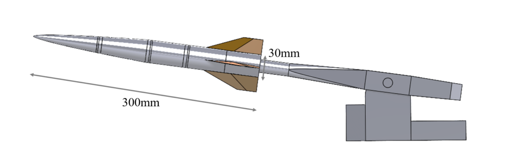
Experimental validation data will be acquired by testing two different models that are based on the outer mold line of the IC3X reference hypersonic vehicle. The models will be a benchtop configuration with no flow, and a wind tunnel model. The benchtop model is designated as IC3X-B to differentiate it from the actual IC3X. The benchtop model is 5 feet in length (40% scale), is made of a single material (plastic or metal), and has an internal structure that was designed specifically to meet the needs of this project. The benchtop model will be subjected to a variety of known structural and thermal loads in the absence of flow, and the resulting deformation will be measured. The wind tunnel model will be 1 ft long, 3D printed from a plastic or elastomer, and is designated as the IC3X-W. Both models will be fitted with a 6 degree-of-freedom force balance to enable measurements of three orthogonal forces and three moments. The models will also be instrumented with a large number of strain and thermal sensors as detailed below.
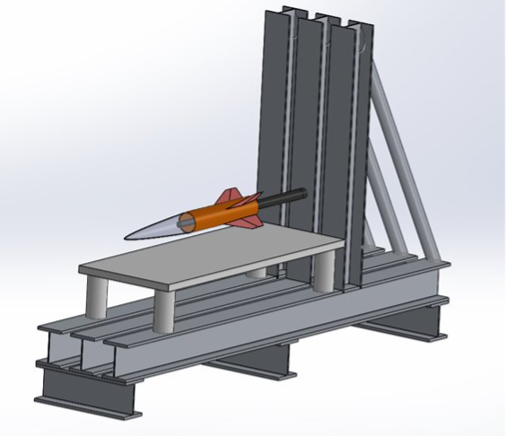
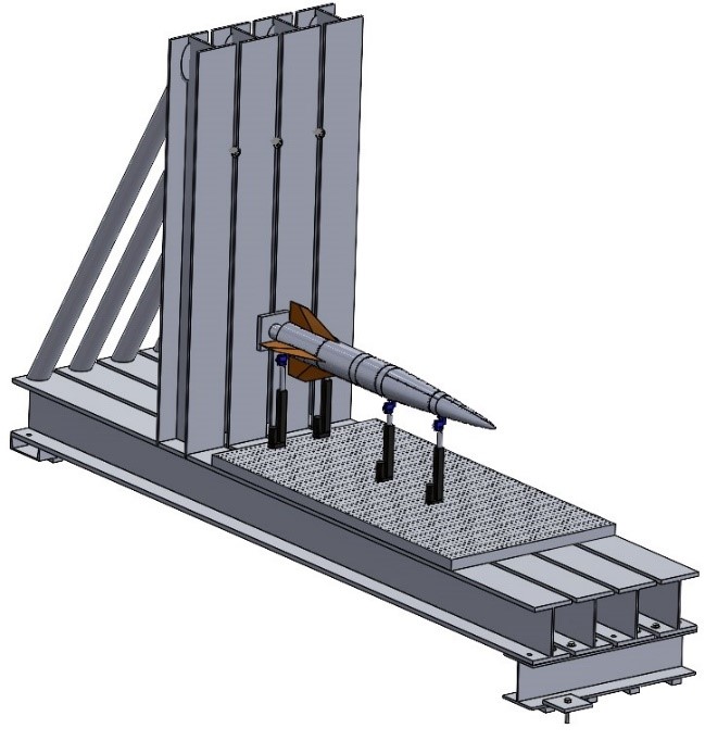
All experiments are performed at the J.J. Pickle Research Campus of The University of Texas at Austin. The benchtop model is attached to the rigid test stand as shown in the accompanying figure. The sting-based 6-DOF force-balance is fixed on one end to the test stand and the model is attached near its center of gravity to the other end. We impose known loads to the model and then measure its deformation with strain sensors. The loads are applied by using four linear actuators, each of which is connected to the model via a uniaxial load cell.
The application of the loads is controlled via a LabView program. A load command is given within the program, which is then sent to a Microcontroller and two PWM motor controllers. The data from the four load cells is read through a National Instruments PXIe DAQ system and serves as the feedback variables.
A fiber optical system is used to obtain local strain and temperature measurements at discrete locations on the inside of the model. A set of four fibers containing eight discrete sensors is used to measure the strain, thus a total of 32 discrete strain measurements can be obtained during each loading case.
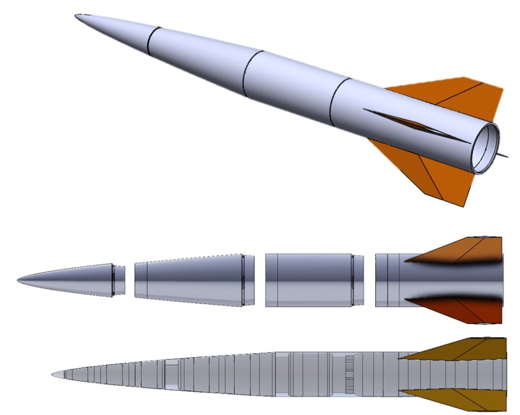
The internal structure of the IC3X-B was designed specifically for this project. To access the interior of the model (to attach and maintain sensors), it is made from four separate pieces, which attach to each other using a tapered twist-lock mechanism, as shown in the figure below. In addition, multiple sections of the wall are reduced in thickness to produce points of flexure. These local flexures lead to large strain values during static loading and offer excellent locations for attachment of the strain sensors, due to the expected high signal to noise ratio.
The benchtop model is fabricated in house using additive manufacturing (3D printing). In-house manufacturing allows rapid design iterations and enables the use of materials with sufficiently low Young’s modulus.
The IC3X-W is a 1 ft long (8% scale) model that is designed to be tested in the Mach 5 wind tunnel. Its internal structure will be mostly identical to that of the larger benchtop model. The fabrication of this model is challenging, as the small dimensions approach the limitations of the additive manufacturing method.
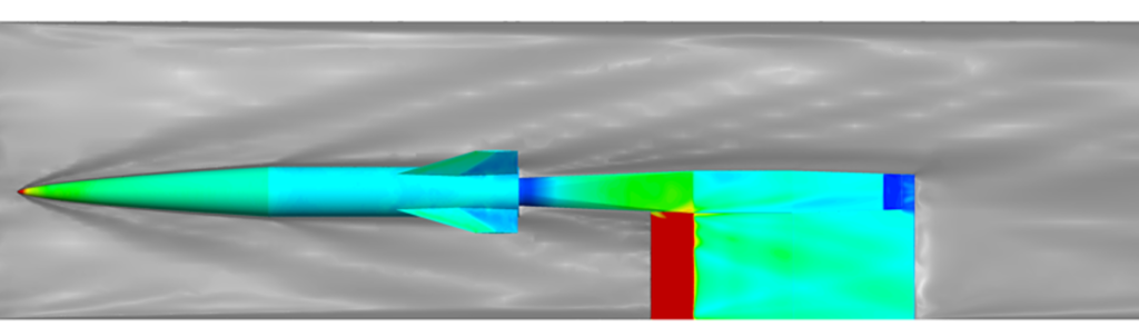
The stiffness of the wind tunnel model (material choice and wall thickness) is based on numerical simulations, which model the structural deformation resulting from flow-induced pressure. The simulations are performed in ANSYS Fluent and ANSYS Mechanical and account for viscous flow effects and structural non-linearities. This model will also be instrumented with fiber optical sensors to obtain strain and temperature measurements on the inside wall. In addition to these discrete sensors, the outside of the model will be measured using pressure sensitive paint and stereoscopic digital image correlation, which obtains distributed surface pressure and strain information.